icona-ricerca_bg
icona-accedi-registrati_bg

Area riservata/Registrati

icona-lingua-ITA

It

Si informano i gentili utenti che, al momento, l’acquisto dei prodotti IGM è effettuabile esclusivamente tramite il sito ufficiale www.igmi.org
Il servizio di vendita diretta su questa piattaforma è in fase di implementazione e sarà reso disponibile prossimamente. Ci scusiamo per il temporaneo disagio.

Geodetic Elements

EPSG codes in use in Italy

The EPSG database includes the coordinate reference systems used in Italy, along with their corresponding projected systems; download the updated guidefor the use of EPSG codes in GIS software and related prj files

Gridded data and coordinate conversion service

GK1 grid (300 km2): covering 10 km around any IGM95 point, with ITALGEO99 geoid model
GK2 grid (300 km2): covering 10 km around any IGM95 point, with ITALGEO2005 geoid model
Grid GK1 (600 km2): covering each sheet of the 1:50,000 map of Italy, with ITALGEO99 geoid model
GK2 grid (600 km2): covering each sheet of the 1:50,000 map of Italy, with ITALGEO2005 geoid model
NTv2 grid: grid portion in NTv2 format covering an area requested by the user by indicating the coordinates of the NE and SO vertexes of the given area of interest (price per km²)

Geodetic Works

Plano-altimetric determination of points
Geodetic and cartographic computation (geodetic computation between points, determination of points, measurement adjustments, deformation modules, etc.)
High-precision measurements for checking the stability of historical buildings and monitoring crustal and surface movements, etc.
Geodetic and geophysics measuring and computing (absolute positioning, magnetic north, gravity)

RDN (National Dynamic Network) Project

In 2009, IGMI updated the European Geodetic Reference ETRS89 to the realization ETRF2000, epoch 2008.0. The new frame was materialized by organizing a network of permanent GNSS stations on the national territory: the National Dynamic Network (Rete dinamica nazionale – RDN). This network system consists of 99 GNSS stations, mostly owned by Public Institutions, which transmit data acquired by satellite systems to a dedicated Data Center specifically set up within the IGMI Geodetic Department.

Locations of the RDN stations, and therefore the consequent definition of the reference frame, resulted by processing the data collected over the four-week period spanning January 1st, 2008. This processing was carried out by the Data Center following the EUREF guidelines (the IAG sub-commission for the European Reference System ETRS89) by using Bernese 5.0 software. Two other Data Centers, namely the G3 group of Milan directed by Prof. F. Sansò, and the Padua group of Prof. A. Caporali, repeated independently the same calculations for an additional control. Final results are shown in the technical report describing, in detail, the development of the RDN installation project.

Since RDN establishment, IGMI has continued to collect data transmitted by the stations and distributes them to users through free access, to the data center of the Geodetic Department

The RDN network is continuously monitored by the Geodetic Department’s Data Center to ensure the quality and availability of data transmitted by the stations. Due to various disruptions, some RDN stations belonging to the original network are no longer active. The Geodetic Department has therefore introduced new sites, restoring the network to a total of approximately 140 stations, in order to preserve a uniform coverage of the national territory. The new network is called RDN2 and the new stations’ data are available in a separate archive at the data center.

The Data Center processes data from the RDN2 network on a weekly basis using Bernese 5.2 software. The results are integrated into the current frame of the International Geodetic System (IGS) and published in ASCII and SINEX format, in a dedicated section, organized according to GPS weeks. Moreover, during 2017, the Data Center reprocessed the entire time series of the weekly solutions, obtaining an aggregate solutions for the positions as well as for the speeds of the RDN network sites. Position and speed estimates, along with the relevant technical documentation, are published in the data center of the Geodetic Department.

See the technical report on the RDN installation project:

High-precision leveling network

The high-precision leveling network was set up between 1950 and 1971, and consisted, at the time of its establishment, of about 13,000 benchmarks materialized along the roads of the national territory. Other leveling networks belonging to the Cadastre, local authorities and research institutes are connected to this network. A major project of complete remeasurement of existing lines and simultaneous establishment of new ones is currently underway, in order to have more than 20000 benchmarks. Elevations refer to 4 elevation systems: Genoa 1942 for continental Italy, Cagliari 1965 for Sardinia, Catania 1956 for Sicily, and Lampedusa 2005 for the Pelagie Islands.

The benchmarks

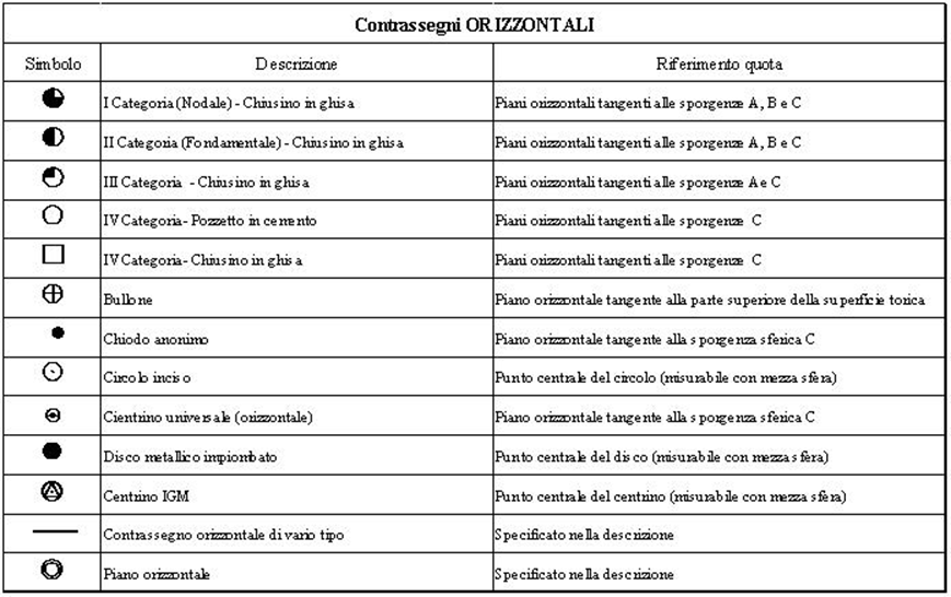
In the geographic search engine, leveling benchmarks are indicated by red or blue round icons. These different symbols are described below:

 benchmark Leveling benchmark measured after 1996

benchmark_old leveling benchmark

Monograph of benchmarks consists of a pdf sheet of useful information that will be send to the costumer.

In each information sheet are indicated:

  • name and specification: name of the benchmark location, a specification can be added in order to better identify the place of materialization;
  • number: the benchmark is identified by an alphanumeric code consisting of 3 different parts separated by underscores: the first part (4 alphanumeric symbols) indicates the line the benchmark belongs to, or the nodal point when the first symbol is “N”; the second part (3 alphanumeric symbols) indicates the line deviation (if any), the third part (4 alphanumeric symbols) indicates the sequential number of the benchmark on the line;

  • Administrative location: Nation, Region, Province and Municipality in which the benchmark falls;
  • Cartographic location: cartographic elements in which the benchmark falls, in the following series: sheet at scale 100,000, map at scale 25,000, sheet at scale 50,000, section at scale 25,000.
  • symbols: up to 4 different symbols for each benchmark; a graphic symbol (see the table below) indicates the benchmark’s materialization, then the evevation up to 0,1 mm. and the description of the exact location of the benchmark.
  • kilometric progression: indicates the kilometric distance from the starting Nodal point of the line;
  • year of measurement: when the height was established;
  • reconnaissance: year of the last survey;
  • coincident: if linked to an IGM95 point;
  • connected vertexes: planimetric/altimetric connection to vertexes of classical network or to leveling benchmarks;
  • Monographic sketch: plan or perspective drawing representing the position of the vertex in the context of the details surrounding it;
  • Geographic coordinates: expressed to the tenth of a sexagesimal second in the ETRF2000 and ROMA40 geodetic systems;


  • one or more pictures of the point;

The following monographs are available:

  • LEVELING BENCHMARKS of the modern High-Precision Leveling Network
  • OLD NETWORK LEVELING BENCHMARKS of the old High-Precision Leveling Network

IGM95 Network

At the end of the last century, the Geodetic Department completed the implementation of an important strategic project concerning the setting up and determination of a new fundamental geodetic network, covering uniformly all Italy and called IGM95. This new network was entirely determined by using GPS differential measurements and it is based on the ETR89 European system by means of EUREF vertexes located in Italy; it is also connected to the traditional triangulation and leveling networks. The IGM95 network consists of 2,000 points covering all Italy and located every 20 km and another 3,000 points, located every 5 km. This increasing of vertex number is carried out only in few regions. All IGM95 points have a MSE of about 5 cm. Some points have a second materialization (i.e. an associated point) near the main materialization (CT-GPS).

The points

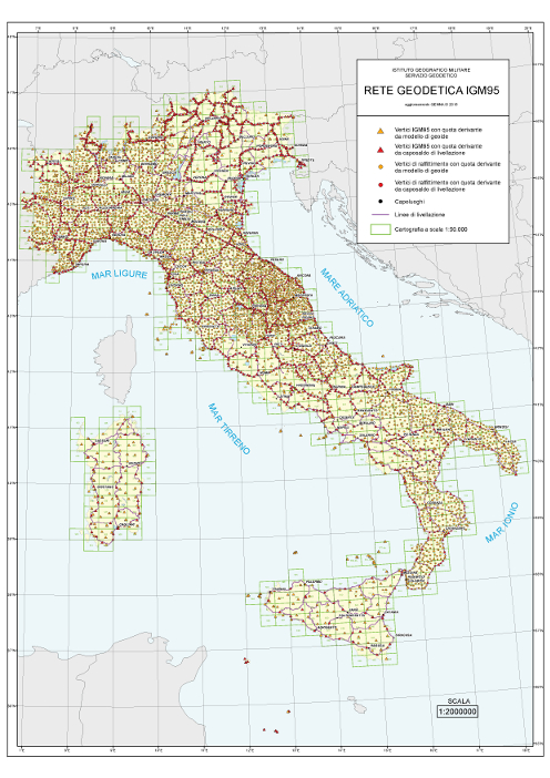
In the geographic search engine, IGM95 points are represented by red or blue triangles and squares. These different symbols are described below:

IGM95_quot IGM95 with height established by leveling
IGM95 IGM95
raffit_quotsecond order vertex with height established by leveling
raffit second order vertex

Monographs of IGM95 points are for sale. The associated point, when existing, is for sale with the main one at the same price. Monograph of IGM95 points consists of a sheet of useful information concerning the point.

In each information sheet are indicated:

  • name and specification: name of the point location, a specification can be added in order to better identify the place of materialization;
  • number: the point is identified by a univocal six-number code; the first three nembers indicate the sheet of the Italian map at scale 1:100,000 where the point is located, the last three numbers are the sheet sequential numbering and the forth number is always greater than five;
  • Cartographic location: cartographic point location: cartographic elements indicating the point location, both in the new series at 50,000 and in its sub- multiple element at 25,000 and in the old series at 100,000 and in its sub-multiple map at 25,000;
  • Administrative location: Nation, Region, Province and Municipality where the point is located, as well as the relevant Carabinieri station;
  • property: name of the owner of the plot of land or building, address included, where the vertex is located;
  • materialization: description of the benchmark indicating the vertex and its location;
  • numerical elements: geographic coordinates in the ETRF2000 and ROMA40 geodetic systems, plane coordinates in the corresponding cartographic systems (TM and Gauss-Boaga respectively), geoid elevation and ellipsoid elevation of the point;
  • access: how to get to the place where the vertex is located (if an authorization is necessary or if there is any restriction);
  • Additional information: any other useful information;
  • Connected vertices: any planimetric/altimetric connection with vertexes of classical network or with leveling benchmarks;
  • planimetry: rank of plan determination among the following ones:
    • Main network (IGM95)
    • Integration point (IGM95 point restoring, permanent station, etc.)
    • Integration point (geotrav, etc.)
    • Second order network
    • Integration point of second order network
  • Altimetry: elevation reference among the following ones:
    • Elevation obtained from leveling benchmark (Fund. network)
    • Elevation obtained from leveling benchmark (old network)
    • Elevation obtained from geoid model (ITALGEO2005)
    • Elevation obtained from geoid model (EGM2008)
  • manufacturer: administration that produced the point;
  • astronomical stations: if any astronomical observation was performed on the vertex;
  • monographic sketch: plan or perspective drawing representing the position of the vertex in the context of the details surrounding it;
  • installation date: date of installation of the point;
  • last intervention: date of the last intervention on the point;
  • one or more pictures of the point;
  • cartographic section indicating the point location.


The following monographs are available:

  • IGM95 point (except for points not belonging to the Second Order Network)
  • IGM95 high-precision point (for points belonging to the Second Order Network)

Fundamental trigonometric network

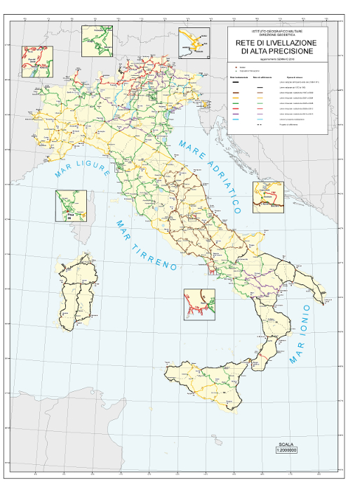
The fundamental trigonometric network, carried out by triangulation and trilateration, consists of more than 20,000 trigonometric vertexes divided into 4 orders and uniformly distributed over the national territory with an interdistance of about 5 km. It covers uniformly all Italy and was first set up between the Italian unification (1861) and 1919. Other national networks such as the Cadastral one are derived from it. This network has an accuracy of a few decimeters in both planimetry and elevation.

In the geographic search engine, trig-points are represented by red or blue squares. These different symbols are described below:

trig-point of certain definition trig-point

Trigonometric vertex of uncertain definition Trigonometric vertex of uncertain definition


Monograph of trig-points vertexes consists of a sheet of useful information concerning the point. In each information sheet are indicated:

  • name and specification: name of the point location, a specification can be added in order to better identify the place of materialization;
  • order: indicates the hierarchy of the determination. The order of importance can be decreasing: I, II, III, IV, Tp5 (checked topographic point), TP (topographic point), CC (established by the state border commission);
  • number: the point is identified by an univocal six-number code; the first three numbers indicate the sheet of the Italian map at scale 1:100,000 where the point is located, the last three numbers are the sheet sequential numbering and the forth number can’t be more than five.;
  • Cartographic location: cartographic elements indicating the point location, both in the old series at scale 100,000 and in its sub-multiple map at scale 25,000, and in the new series at scale 50,000 and in its sub- multiple element at scale 25,000;
  • Administrative location: Nation, Region, Province and Municipality in which the trig point falls, as well as the relevant Carabinieri station;
  • property: name of the owner of the plot of land or building, address included, where the vertex is located;
  • reference plane: description of the horizontal element to which the elevation refers;
  • adjustment: indication on the calculation that provided the planimetric determination;
  • numerical elements: geographic coordinates in the ETRF2000 and ROMA40 geodetic systems, plane coordinates in the corresponding cartographic systems (TM and Gauss-Boaga respectively) and vertex elevation;
  • history: main events in the vertex’s history;
  • materialization: description of the elements (objects or symbols) indicating the vertex;
  • access: how to get to the place where the vertex is located (if an authorization is necessary or if there is any restriction);
  • Additional information: any other useful information;
  • Astronomical stations: if any astronomical observation was performed on the vertex;
  • Monographic sketch: plan or perspective drawing representing the position of the vertex in the context of the details surrounding it;
  • Last intervention:last intervention: description of the last intervention performed on the vertex.


The following monographs are available:

  • TRIGONOMETRIC VERTIXES
  • TRIGONOMETRIC VERTEXES OF UNCERTAIN DEFINITION (materialized approximately or of inferior order than III and established before 1940)

Reproductions of documents from the historical archives

In the Historical Archives of the Geodetic Department is stored the documentation concerning geodetic works from the mid-nineteenth century to the present. The documentation is mainly related to works carried out on Italian territory, but data on former Italian colonies across the sea can also be found.

The following documents can be requested:

  • Reproduction of documents from the historical geodetic archive in A4 format
  • Reproduction of documents from the historical geodetic archive in A3 format

VERTO Software

Verto family software enables coordinate conversions between the most widely used reference systems in Italy: Rome40, ED50 and ETRS89, the latter in the ETRF89 and ETRF2000 realizations.
List if software currently available:

MAIN DIFFERENCES

  1. Verto2k and Verto3k are chargeable, and gridded data must also be purchased separately in order to carry out coordinate conversion; Verto on Line is free.
  2. Planimetric results are identical for the 4 reference systems for both Verto2k and Verto3k and Verto on Line.
  3. Verto2k and Verto3k also convert elevations by means of geoid models; Verto on Line does not carry out elevations’ conversions.
  4. Verto2k and Verto3k accept entered coordinates of a point, .txt files, and excel files as input formats; Verto on Line can process many types of both vector and raster files.

Product Categories